Understanding CAN Bus Communication in Aerial Work Platform Electrical Systems
2026-09-04
Aerial Work Platform Electrical Systems-Modern aerial work platforms are no longer controlled by simple switches, relays, and hydraulic valves alone. On Genie, JLG, Dingli, Haulotte, Skyjack, LGMG, Zoomlion, Sinoboom and many other machines, electronic controllers have become the core of the machine control system.
The ground control unit, platform control box, ECU, joystick, motor controller, display, sensors and other electronic components need to exchange information continuously. In many machines, this communication is handled through the CAN Bus.
For aerial lift technicians and parts suppliers, understanding CAN communication is becoming increasingly important. A CAN fault may look like a defective control board, but the real problem could be somewhere else in the electrical system.
CAN Bus in an Aerial Work Platform
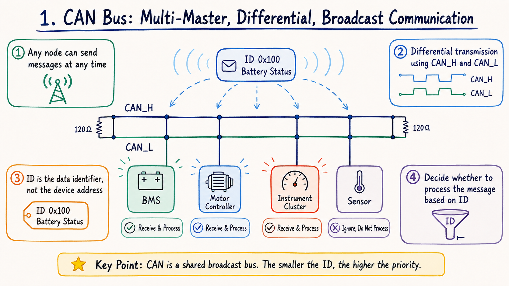
CAN stands for Controller Area Network. It allows multiple electronic components to communicate over the same network instead of requiring separate signal wires between every device.
A typical aerial work platform may include several CAN-connected components:
Ground control module
Platform control module
Main ECU or control board
Joystick controller
Motor controller
Display module
Tilt and angle sensors
Load sensing components
Battery management system
Other intelligent sensors and I/O modules
For example, when an operator moves a joystick on a boom lift, the joystick does not necessarily control a hydraulic valve directly.
Instead, the joystick position may be converted into an electronic signal and sent through the CAN network. The main controller receives this information, checks safety conditions and then commands the appropriate output or motor controller.
This happens continuously while the machine is operating.
Aerial Work Platform Electrical Systems
CAN_H and CAN_L
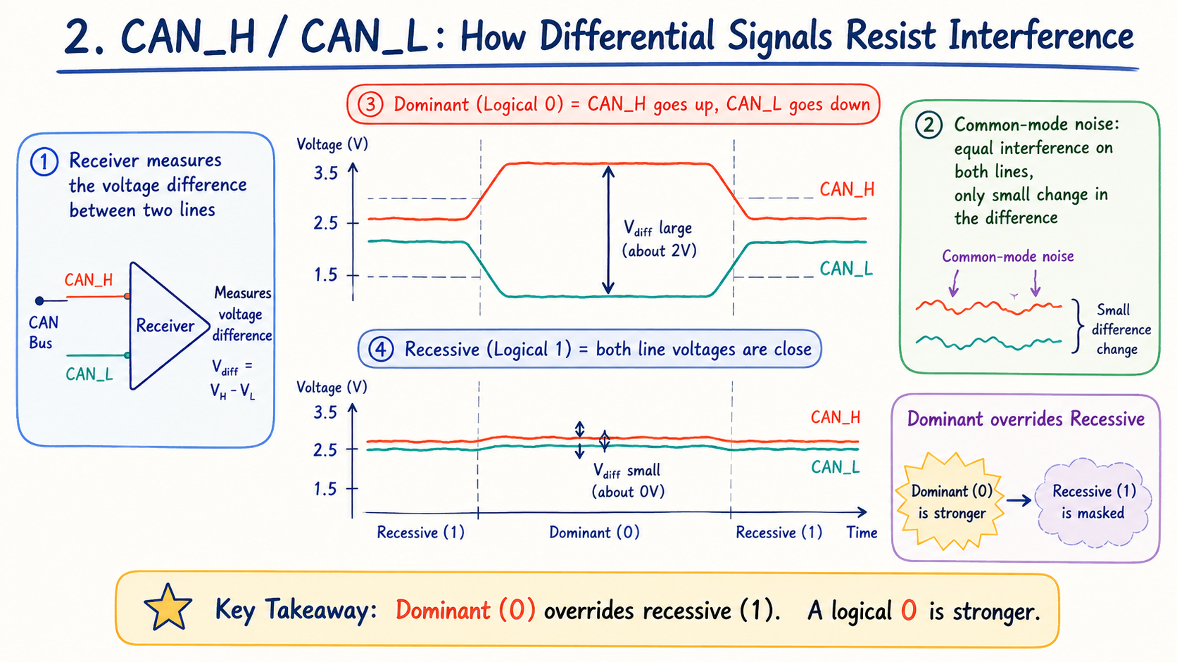
Most CAN networks use two communication wires called CAN_H and CAN_L.
These wires carry differential signals, making CAN communication resistant to electrical interference. This is particularly useful in aerial work platforms because motors, hydraulic pump systems, contactors, chargers, solenoid valves and high-current battery cables can all create electrical noise.
However, CAN wiring and connectors are also common sources of trouble.
A damaged harness, corroded connector, loose terminal or water inside a control box can interrupt communication between modules even when the ECU itself is working correctly.
This is why replacing a controller should not always be the first step when a CAN communication fault appears.
Aerial Work Platform Electrical Systems
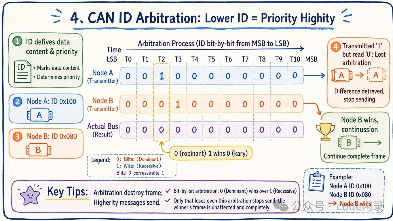
Why Technicians Often Measure 60Ω
One of the most practical CAN Bus tests is resistance measurement.
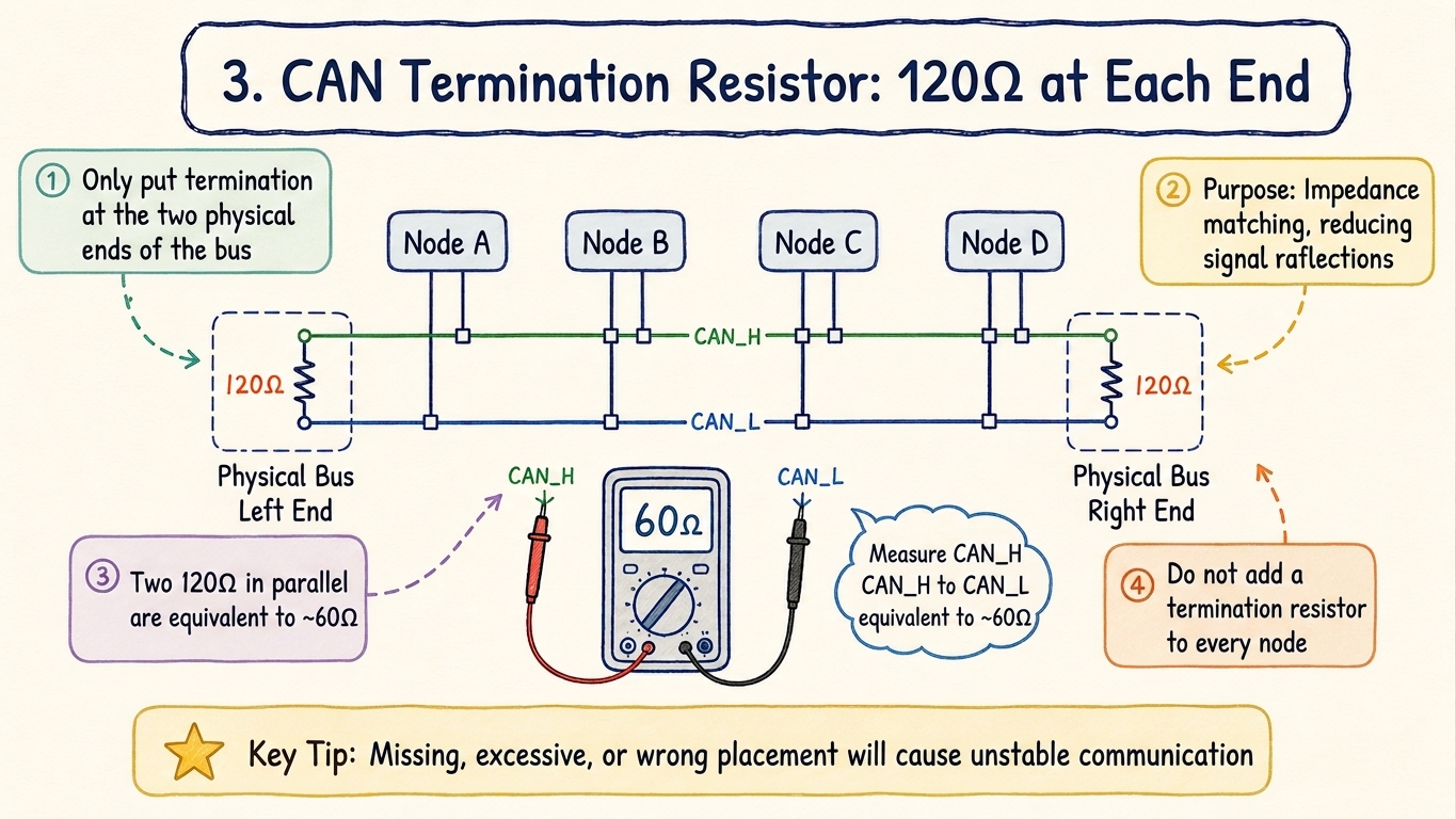
A conventional CAN network normally uses a 120Ω termination resistor at each physical end of the bus. These resistors reduce signal reflections and help maintain reliable communication.
Because the two 120Ω resistors are connected in parallel, the resistance measured between CAN_H and CAN_L is normally around 60Ω when the system is powered off.
120Ω + 120Ω termination → approximately 60Ω measured between CAN_H and CAN_L
If the measurement is approximately 120Ω, one termination resistor or part of the network may be disconnected.
A reading around 40Ω may indicate that an additional termination resistor is present.
A very low resistance may indicate a short circuit, while an open or extremely high reading may point to broken wiring or a disconnected CAN network.
The exact design varies between manufacturers and machine models, so the machine wiring diagram and service manual should always be considered.
Aerial Work Platform Electrical Systems
How Controllers Share the Same CAN Network
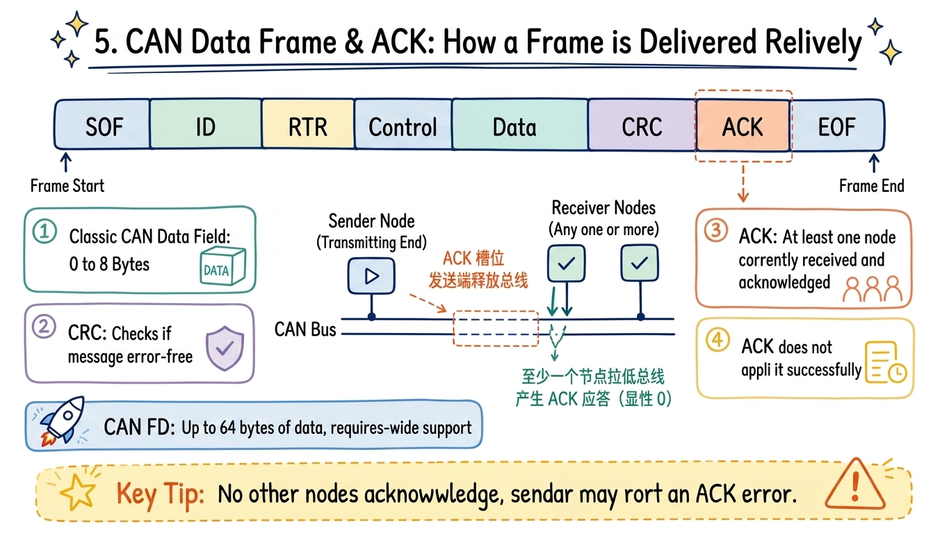
An aerial work platform may have many electronic modules communicating at the same time. CAN uses message IDs and arbitration to prevent these messages from interfering with each other.
Each CAN message has an identifier. In CAN arbitration, a lower numerical ID normally has higher priority.
For example:
Node A: CAN ID 0x100
Node B: CAN ID 0x080
If both attempt to transmit at the same time, the message with ID 0x080 wins arbitration and continues transmitting.
The other controller does not create a collision or destroy the message. It simply stops transmitting and tries again later.
This allows multiple controllers, sensors and other electronic components to operate efficiently on the same communication network.
Aerial Work Platform Electrical Systems
Data, CRC and ACK
A CAN message contains more than just the operating data.
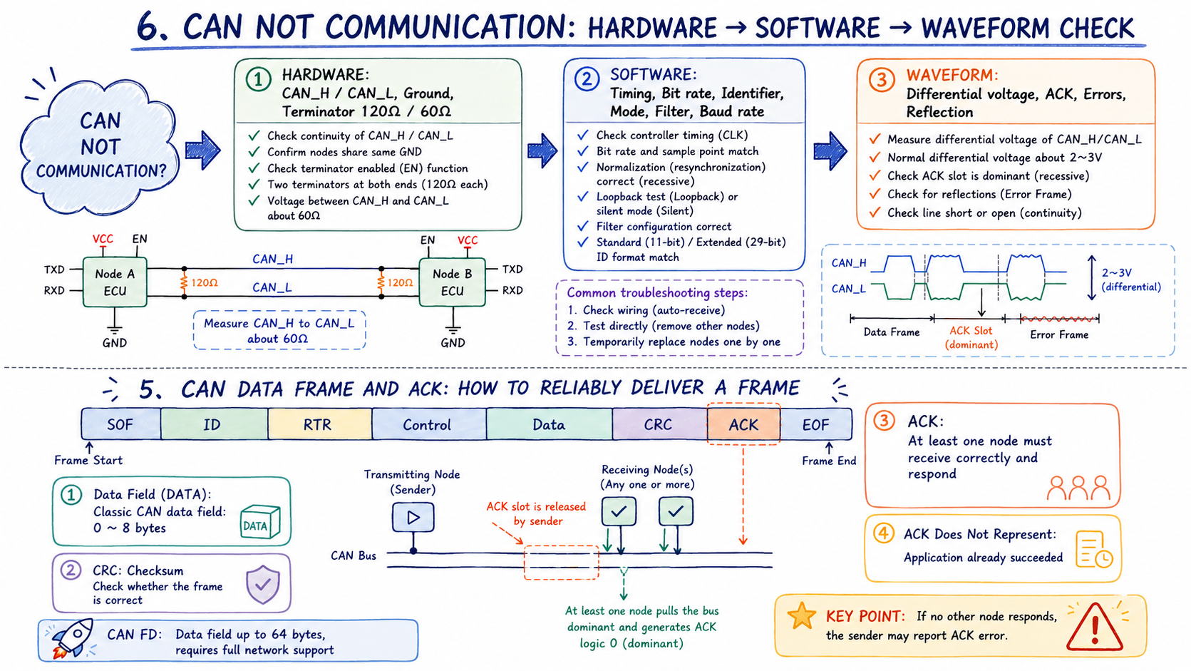
A typical CAN frame includes the message ID, control information, data, CRC and ACK.
The data section can carry information such as joystick position, steering commands, drive requests, boom position, sensor values, battery status and machine operating conditions.
CRC is used to detect transmission errors.
ACK, or acknowledgment, confirms that at least one other CAN node correctly received the CAN frame.
This distinction is important during aerial lift troubleshooting.
An ACK confirms communication at the CAN level. It does not necessarily mean that the requested machine function was successfully performed.
For example, a controller may correctly receive a lift-up command but still prevent the machine from lifting because of a tilt condition, overload signal, emergency stop, low battery voltage or another safety interlock.
The communication can therefore be completely normal even when a particular machine function does not operate.
Aerial Work Platform Electrical Systems
Why a CAN Fault Does Not Always Mean a Bad ECU
This is one of the most common misunderstandings when diagnosing aerial work platform electronic systems.
Suppose a machine displays a controller communication fault. It is easy to assume that the corresponding ECU or PCB has failed and needs replacement.
But there are several other possibilities.
The controller may have lost its power supply.
The ground connection may have excessive resistance.
CAN_H or CAN_L may be damaged.
A connector may contain water or corrosion.
A terminal may be loose.
One of the termination resistors may be missing.
Another CAN-connected component may be pulling down the entire network.
Only after these possibilities are checked should the controller itself become the main suspect.
This is especially important when replacing expensive electronic parts. Installing a new ECU will not solve the problem if the actual fault is a damaged CAN harness or unstable power supply.
CAN Communication and Replacement Electronic Parts
CAN communication also matters when selecting replacement aerial lift electronic parts.
A control board may physically fit the machine and use the same connector, but this does not automatically guarantee compatibility.
Depending on the machine, compatibility may also involve hardware generation, software version, CAN communication protocol, machine configuration, calibration and parameter programming.
This applies to many types of electronic parts, including:
ECUs and main control boards
Ground control modules
Platform control modules
Joystick controllers
Motor controllers
Display modules
CAN sensors
Handheld analyzers and diagnostic tools
For some replacement controllers, programming or configuration may be required before installation. In other cases, different machine generations may use visually similar control boards but different communication settings.
This is why part number, machine model and serial number are important when confirming an electronic replacement part.
A Practical CAN Troubleshooting Process
When troubleshooting a CAN communication problem on an aerial work platform, technicians can follow a simple sequence.
First, check the battery and system voltage. Low or unstable voltage can cause electronic controllers to reset repeatedly.
Next, verify the power supply and ground at the controller. Then inspect CAN connectors and wiring for loose terminals, corrosion, damaged pins, water ingress and broken harnesses.
With the machine safely powered off according to the manufacturer’s procedure, measure the resistance between CAN_H and CAN_L. On a conventional CAN network with two 120Ω termination resistors, approximately 60Ω is normally expected.
If the wiring and termination appear correct, individual CAN devices can be investigated according to the manufacturer’s diagnostic procedure.
For intermittent or difficult problems, a CAN analyzer or oscilloscope can help determine whether messages are being transmitted correctly and whether signal quality is stable.
The key is to diagnose the CAN network as a complete system rather than simply replacing electronic parts one by one.
Conclusion
CAN Bus has become an important part of modern aerial work platform electrical systems. ECUs, control boards, joysticks, displays, motor controllers and sensors often depend on this network to work together.
For technicians, understanding CAN_H and CAN_L, 120Ω termination resistors, the typical 60Ω resistance measurement, CAN IDs, CRC and ACK can make electrical troubleshooting much more efficient.
For replacement parts, CAN communication is equally important. A control board must not only fit the connector; it must also communicate correctly with the rest of the machine.
At RQ Parts, we focus on electronic parts for aerial work platforms, including control boards, ECUs, controllers, joysticks, displays, sensors and related electrical components for Genie, JLG, Dingli, Haulotte, Skyjack, LGMG, Zoomlion, Sinoboom and other equipment.
Understanding how these components communicate inside the machine helps us do more than simply match a part number. It helps us better understand compatibility, installation and real-world troubleshooting of aerial work platform electrical systems.